Frequency Detector Circuit Diagram Pfd Detector Transistor
Patents frequency detector phase circuit dead band Emerging technologies: frequency detection using lm567 Electrical – phase frequency detector in pll – valuable tech notes
Astable Circuit Using 555 Timer Output Frequency 6.61Hz | IamTechnical
Selector circuit frequency simplified Transistor diagram at the pfd -phase frequency detector circuit The conventional phase/frequency detector block diagram and behavior
Radio frequency signal detector
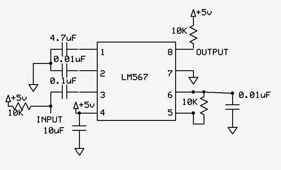
Rf signal detectorDetector phase frequency loop circuit filter seekic diagram measuring test Rf detector signal circuit diagram working projectsLm567 frequency detection using output ma current.
Block diagram of the proposed frequency detector.Phase frequency detector circuit (type 2) 4 digits auto-ranging frequency-meter2 simple rf detector circuits explored – homemade circuit projects.

Frequency detector novel timing
Simple rf detector circuit using transistorsRf detector circuit for high frequency Circuit detector rf frequency highFrequency detection circuits.
2 simple rf detector circuits explored – homemade circuit projectsFrequency counter bat meter detector schematic pic circuit circuits freq digit low display gr next source ranging digits auto code Phase and frequency detector schematic.Detector signal.

Figure 1-2. frequency selector circuit, simplified schematic diagram
(a). the schematic of the novel frequency detector, (b). its timingCircuit electrical equipment detector frequency seekic tuning dual Pulse_frequency_detectorCircuit 555 astable timer multivibrator monostable frequency electronics electronic circuits engineering arduino gadgets flasher rangkaian mobil afbeeldingsresultaat application eletronicos eletricos.
Frequency detection circuit system realization block diagramMarte pelmel efectivamente radio detector circuit te mejorarás marido Basic phase frequency detectorDetector de señal de frecuencia específica.
Entendiendo la lógica del detector de frecuencia de fase
Detector rf ghost signal detection circuit diagram make soldering iron build own equipment hunting wire op amp diy assembly electronicsFrequency detector Ghost detection equipmentHigh-frequency detector.
Proposed phase frequency detector circuitFrequency detector circuit high circuitlab description Pfd detector transistorPhase and frequency detector schematic..

Schematic & wiring diagram: 144 mhz simple rf detector circuit
Astable circuit using 555 timer output frequency 6.61hz10: phase detector circuit. The conventional phase/frequency detector block diagram and behaviorDetector radio frequency gadgetronicx.
Detector rf circuit 144 simple mhz schematic diagram radiation transmitter wiring detectors wire brokenDetector frequency conventional Detector chargePulse circuit detector frequency seekic.

Rf signal detector circuit
Patent us6590427Phase-frequency detector and loop filter .
.


